Harley Davidson Forums banner

Rebuilding a Keihin CV40 carb

95K views 53 replies 26 participants last post by  FritzHD  
#1 · (Edited by Moderator)
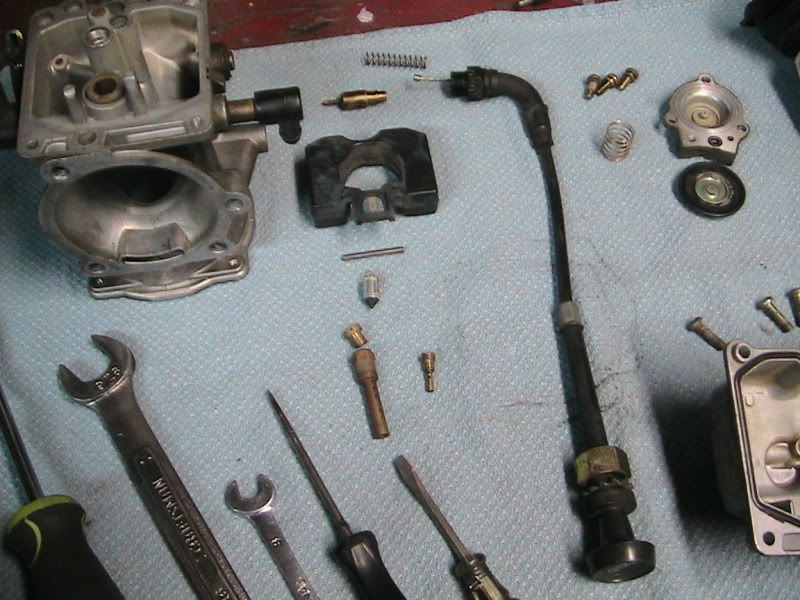
Rebuilding your CV40 carb isn't rocket science. It's simply a matter of taking the carb apart, cleaning items that are prone to poor performance if exposed to dirt for decades and rejetting it properly upon reassembly. Float adjustment only has to be set of it's messed with, you hit the float and bend the tab, or the platic float develops a leak and becomes heavy. One other reason would be is if the needle were bad and needed to be replaced, and in this case, that happened. Start with your typical, CV40 carb. The Keihin CV40 was introduced in 1988 on the XL models, however did not originally have an accelerator pump. 1989 to 2006 models did. This is your typical CV40 carb. This model is a 1992. (Special thanks to LilJo!!)
Image


Image


Image


Image


Tools needed will be:

1.) Medium straight blade screwdriver
2.) Medium phillips screwdriver
3.) Small straight blade screw driver
4.) 8mm wrench
5.) pick
6.) can carb cleaner (2+2 is my favorite flavor)
7.) Thread lock red (For fuel elbow replacement only.)
8.) 9/16" wrench
9.) fuel elbow removal tool, or a vice, if replacing the fuel elbow.

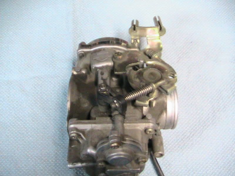
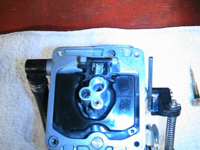
When you take the bowl off, you'll see the flat, main jet, pilot jet and needle in place. The seam of the float should be about level with the side of the carb casting, or just a tad below it.

NOTE ARROW AT LEFT OF LEFT FLOAT PIN TOWER. YOU NEED TO PRESS THE PIN TO THE RIGHT. IF NOT, YOU'LL BREAK THE TOWER, AND THE CARB IS JUNK!! You can just see the little arrow, pointing to the right, cast into the carb body.

Image


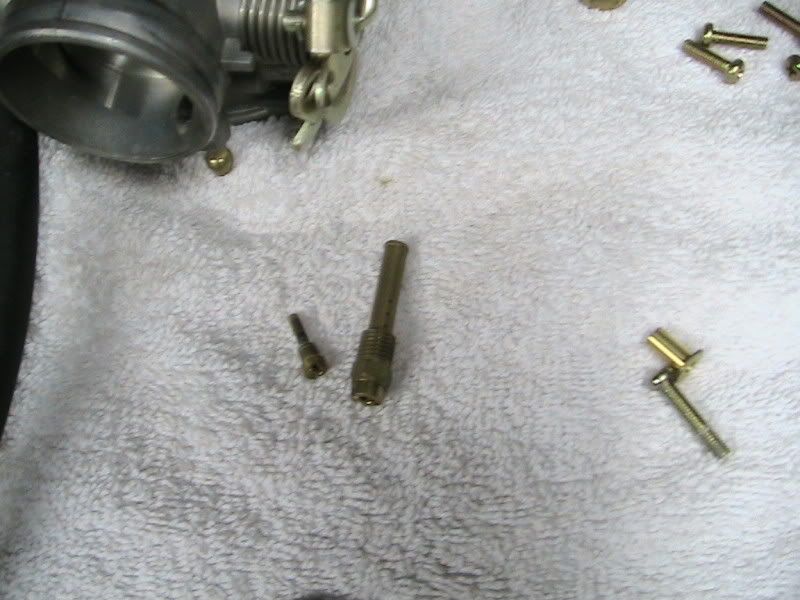
Remove your jets using a good screwdriver, and the appropriate size. If not, you can strip them (Brass is soft) and then you have issues.

Image


Not the larger one is the MAIN JET still screwed into the EMULSION TUBE. The smaller jet is your PILOT JET.

Image
 
  • Like
Reactions: #1mike
#2 · (Edited by Moderator)
Disassemble your carb, piece by piece, laying your parts out on a clean, open working area. If you lay them out in the order they cam off the carb, you'll have no issues with putting them back in, in the correct order.

Image


Image


Image


Image


Once done, you'll have a smaller carb body, that needs to be thoroughly cleaned, insode and out, making sure to pass air through all the air bleeds and ports. Remove everyting, including the main jet, pilot jet, emulsion tube (main jet scews into it) and the diaphram and associated parts.

Clean the body and bowl with carb cleaner and a tooth brush. I use a series of brass and mild steel brushes. Afterwards, I have a polishing process I developed, that's fast and efficient, making the carb look like new again.

Image


Image


Image
 
#3 · (Edited by Moderator)
One thing you may want to do, is to remove the air fuel mixture screw, and clean and inspect the tip. In the screw passage, there's a brass needle screw, a spring, an o-ring and a washer. Note the order they came out in. Note if there's any damage to the screw as it's thin and fragile. Clean screw and replace all removed parts in the order they were removed. Kits for rebuilding will come with a new o-ring. Replace it if removed.

Image


Remove the "choke" cable. It is removed by turning the plastic 9/16" nut that threads into the carb body. The brass pintle on the end is what is moved within the passage when you pull the knob, with the thin needle end allowing more fuel to enter the carb, and the wider brass part allowing for more air. That's why this isn't a "choke", rather an ENRICHENER. It adds fuel, not cuts off air the supply (butterfly) making the mixture richer.

Make sure to clean the enrichener port out well with carb cleaner, and clean the pintle well, also.

Image
 
#45 ·
One thing you may want to do, is to remove the air fuel mixture screw, and clean and inspect the tip. In the screw passage, there's a brass needle screw, a spring, an o-ring and a washer. Note the order they came out in. Note if there's any damage to the screw as it's thin and fragile. Clean screw and replace all removed parts in the order they were removed. Kits for rebuilding will come with a new o-ring. Replace it if removed.
dave, one question. i have remove the air fuel mixture screw but i didnt found a washer?

so i buy a new rebuilding kit but i dont know the order. which is the right one.

-screw, spring, washer, o-ring

-screw, spring, o-ring, washer

-screw, washer, spring, o-ring

could anyone help me?

thanks and all the best pat
 
#4 · (Edited by Moderator)
Once the carb body and bowl are cleaned and polished, and the carb throat is polished, I'm ready to reassemble. In the case of this carb, the fuel inlet was plastic. This needs to be replaced. The old elbow id removed and a CV-Performance brass elbow is put in its place. Refer to the STICKY on elbow replacement.

Image


Image


Image


Image


The accelerator pump 3-screw cover is removed and the diaphram is inspected. Keep in mind that the diaphram can delaminate and peel apart. If you see this, regardless of being only one side, then replace it. There's a small o-ring in between the cover and the carb bowl that needs to be replaced when removed. In this case, I also replaced the hardware.

Image


Image


The emulsion tube, main jet, pilot jet, needle and float are replaced. Keep in mind, when removing the float pin, THE PIN IS REMOVED FROM THE LEFT TO THE RIGHT, IF THE PIN TOWERS ARE FACING YOU AND THE FLOAT IS FACING AWAY FROM YOU. If you try to force it the other way, you'll break a tower and the carb is now JUNK. There's an ARROW pointing towards the way the pin is to be removed.

Once all parts are installed, replace the bowl, accel pump bellows, accel pump actuator shaft and 4 screws.

Image
 
#5 · (Edited by Moderator)
Replace the slide and diaphram. I polish the slide, and bevel the leading edge for better air flow. Make sure on reinstall, the lip of the diaphram fits into the upper housing groove, or you'll tear it and it'll leak. It's a $60 part. Keep that in mind. As the cover is placed on it, you can push the rubber end back into the groove with a small screwdriver. As the lip seats, you'll see the cover meet the carb housing.

Image


Image
 
#6 · (Edited by Moderator)
Install your main jet needle, the spring seat and the spring. I used an XL needle for this build as it works well with giving good midrange fuel with no bog. If your engine is stock, install the needle (XL PT# 27094-88). FOr larger engines. cammed engines, I use a .050" shim under the needle to add just a touch more fuel.

Image


Can be seen in throat, into main housing:

Image


You can either install a DynoJet spring which is shorter and a lighter spring rate, (8.8 onces for 3" compression and 5" long VS stock which is 12.5 onces for 3" compression and 5.5" long) a stock spring, or take a stock spring, cut off 3 rings from it, and your slide will react faster, giving similar results as the DynoJet spring.

Now that all your parts are inside the top of the carb, the cover can go back on, sa can the right side cable cradle.

Image
 
#7 · (Edited by Moderator)
Install your chokepintle and spring back on the cable, and reinstall back on the carb. GENTLY tighten the plastic nut back into the carb housing.

Image


I generally set the air/fuel screw 2 turns out to start. This carb is set up for a Big Twin, with a 190 main, an XL needle shimmed .050", a 48 Pilot jet, new accel pump diaphram and a stock diaphram spring, and no drilled slide air-bleed hole.

This is your completed carb:

Image


Image


Image


Image


Image


Image


Image
 
  • Like
Reactions: Squint and Dyna FXD
#8 ·
OUTSTANDING, Dave!

Now I'm REALLY glad you got that carb. Well documented, this ought to help a lot of people out. Thanks for posting, man.

A LOT of gasoline has gone through that carb. And now it looks better than new.
 
#9 ·
Excellent Dave! :thumbsup

What's the polishing process you use?
 
#11 ·
I see what you mean Dave, that little brush really works well. Looks like a new carb....:thumb
 
#12 · (Edited by Moderator)
Yeah.....I'm fuzzy as a peach about the job it did, Phil. Offer still stands....!!
 
#15 ·
This is what he posted.....
If your engine is stock, install the needle (XL PT# 27094-88). FOr larger engines. cammed engines, I use a .050" shim under the needle to add just a touch more fuel.....
 
#18 ·
Hahahaha.....It's ok, Phil. I posted at the same time you did. :D
 
#19 ·
P.S. i ordered both parts we discussed earlier....an a bottle of Jack. fer installation purposes...:thumbsup
 
#22 ·
Jetting is like math: Engine mods = fuel necessity. Even though I may recommend certain jetting, a Dyno tune will prove or disprove a bench tune, and adjustments can always be made to gain that liitle bit more of torque or power.

I only get the bike within 90-95% of the needed range. I'm sure if I suggest a 48/185 set up with a .050 shim on an XL needle or, or use various other needles, there's always a slight improvement that could be made, that's only going to be found on a Dyno, using a gas analyzer.

Will the rider actually "feel" the difference in that change. Maybe....maybe not.

If it wasn't so expensive... I'd recommend Dyno tuning to everyone. It's amazing how we assume any mod we do with GAIN us power/torque, and then to see how some mods actually cause us to LOSE power and torque.

You'll really get no better tuning then to have it done by an exact science, with real world results, not trusting your "Ass-Dyno".
 
#23 ·
Congrats Dave, great informative thread.
 
#27 ·
2012 Camaro. V-6. 300 Hps...........

A far cry from the V-6's of 1980's that couldn't pull a sick whore off a toilet seat.
 
#29 ·
180 HPs if she's addicted to crack, lost her pimp and has at least 4 prostitution convictions, and is currently on parole....... There's a flow-chart somewhere to figure this out.
 
#30 ·
Great description Dave, thanks. Can you tell us which way the the needle jet above the emulsion tube goes, since it likes to drop out when you're not looking, when you take the emulsion tube out. I think it goes in with the longer section up, so the larger hole is up as well. Can you confirm or correct that?
 
#32 ·
The needle goes in, from the slide diaphram, tip first, down into the carb throat, then into the emulsion tube.

If you simply take the emulsion tube out, the sleeve can drop out, but the needle CAN'T come out that way, as it sits in the diaphram base, as it rises and falls with the slide diaphram.

You can see, with the slide diaphram removed, the needle comes out with it. It can't slide downward any father, due to the "hat" on the end.

You can also see the "seat" (Bright silver) in the carb throat that the needle slides into, which is kept in place by the emulsion tube. (Needle Jet)

The only possible way a needle could "drop out" after removing the emulsion tube, is if it were a DynoJet needle (with a clip to adjust height) that the clip came of of, allowing the needle to pass through th diaphram hole.

Image
 
#34 ·
I read his post again and see why I answered the way I did....

Great description Dave, thanks. Can you tell us which way the the jet needle goes, since it likes to drop out when you're not looking ,when you take the emulsion tube out. I think it goes in with the longer section up, so the larger hole is up as well. Can you confirm or correct that?


I see, now. :D

The needle is what I was refering to.:thumbsup

Correct....The "needle Jet" can fall out. Small end down, larger end up.
 
#35 ·
I'm getting old and confused. I was referring to the needle jet, not the jet needle. I even carefully edited my original post from "needle jet" to "jet needle" to make matters worse.

Thanks for sorting me out Dave and Cobra. Small end down, big end up, I'll check my carb tonight, as mine did fall out, and I think I got it right, but who knows.
 
#37 ·
Depending on the needle, you will. With the right needle and height, the midrange lean issue becomes nonexistant.